The increasing number of registered electric vehicles is driving rapid growth in supporting infrastructure as well. The EU Green Deal targets 1 million charging points by 2025. These charging stations must bill according to strict requirements of, amongst others, the “Eichrecht”, in accordance with directive 2014/94/EU of the European Parliament on the development of infrastructure for alternative fuels. This directive mandates precise energy measurement by the charging stations, respectively their integrated energy meters. To ensure adherence to government/EU requirements for the finished product, it is advisable to already accompany the R&D process with a suitable way of verifying compliance in order to prepare for mandatory type examination certification.
Figure 1 illustrates the connection of an EV charging station to the grid and the EV with the energy flow while charging. A precise power measuring instrument like the LMG600 series power analyzer can be integrated into a compliance test bench by charging station manufacturers and certifying institutions. It can serve as traceable standard for type examination certification, and it is a tool of choice to verify the proper charging functioning once doubts arise.

Figure 1: EV charging station
Measuring setup
Charging stations are equipped with a single or multiple charging plugs of type 2, CCS, CHAdeMO or other to provide AC and/or DC charging. Integrated certified energy meters for each charging plug measure the energy consumed for the complete charging process. The meter communicates its reading to the system backend for billing purposes. A typical assembly is shown in Figure 2.

Figure 2: EV charging station energy meter structure
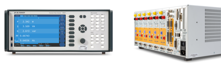
The module B, respectively EU-type examination test for certification, stipulates to verify the accuracy of the complete charging process by comparing the energy metered at each charging port with the energy measured by a reference instrument. This can be a precise power analyzer like the LMG671 wired between the energy meter and electric vehicle. Figure 3 shows a possible measuring setup with an LMG671 power analyzer as reference instrument.
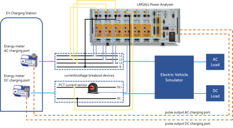
Figure 3: Measuring setup with LMG671 and PCT current sensor
The voltage and current signals are fed into the power analyzer via breakout boxes. Voltage drops that may occur are typically negligibly small. For AC type 2 charging plugs, the current must not exceed 32 A and can directly be connected to the power analyzer’s inputs[1]. Particularly fast DC charging results in current values of several 100 A which require a very accurate current sensor, like the PCT sensor with its outstanding Flux-Gate technology.
Additionally, the energy meter's pulse output is connected to the LMG671 process-signal-interface (PSI) switching input[2], allowing the analyzer to capture the pulses during the complete charging process to determine the energy metered by the charging station. The type examination test procedure specifies a measurement over a minimum number of leaps of the lowest value digit, which corresponds to a minimum number of pulses. This number depends on the device to be charged and the point of operation chosen. The higher the charging power, the higher the prescribed minimum number of pulses. Otherwise, the observed time window will be too short, and the uncertainty of the internal clock will have an undue influence on observed measurement accuracy. The overall energy measurement includes the charging station’s ramp up as well as the ramp down as shown in Figure 4.
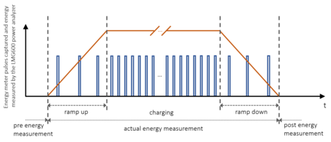
Figure 4: Energy meter pulses captured and energy measured by the LMG600 power analyzer
The LMG671 switching inputs are sampled with 150 kHz. Standardized energy meter pulse signals will be reliably captured and counted. Depending on the charging power level and specified pulses per kilowatt-hour of the integrated energy meter, the fastest measuring cycle time of 10 ms (or 20 ms considering a 50 Hz signal) allows to count the pulses captured almost one by one. This is important to ensure the number of captured pulses during the energy integration interval is accurate.
The LMG600 series power analyzer provides highly precise AC and DC power and energy measurements and a full range of functions to perform compliance tests on charging stations. All required signals specified in the type examination test, in accordance with related standards as EN 50470-3 and IEC 61851-23, will be measured and processed. The process-signal-interface can directly and simultaneously capture the pulse output of several digital energy meters that are installed in charging stations in order to determine their energy measured. The fast and functional Gigabit-Ethernet interface ensures reliable integration into the test bench setup for data exchange and data post-processing. ZES ZIMMER provides a generic python script for a compliance verification. Additional software engineering support can be offered to implement specific test bench requirements.
Test bench integration and evaluation
In order to fully integrate the LMG600 power analyzer into a remote-controlled test bench environment, ZES ZIMMER can provide a generic script covering the described automized verification procedure upon request. It comes with a ready-to-use and well documented python class, including functions as open and close interface, write, read and many more. We can offer software engineering support for customization in accordance with your specific setup and test procedure, including subsequent evaluation of results, exported into any common format needed (CSV export already implemented). The following automized functions are possible for implementation:
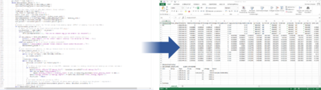
Figure 5: Example of python script with export of measurement data and evaluation results
The fast and functional Gigabit-Ethernet interface of the LMG600 ensures reliable integration into the test bench setup for data exchange and data post-processing. ZES ZIMMER provides a generic python script for a compliance check. Additional software engineering support can be offered to implement specific test bench requirements.
Measuring uncertainty
The combined accuracy of power analyzer and current sensor used has to be very high, otherwise the error introduced by both dominates the overall measured deviation of the charging station’s metered energy. The overall deviation to be finally examined is calculated as:
Deviation = Deviation + Measuring uncertainty
overall energy meter power analyzer + current sensor
Such measurement uncertainty considerations can be calculated even for each measuring point and measuring cycle during the charging process. While modern power analyzers can assist with measuring range selection (AutoRange), this supporting automatism is not always beneficial. At fast and continuously changing measuring points, such as the ramp up and ramp down phases shown in Figure 4, Autorange can result in frequent range changes, which in turn causes gaps in the measurements due to the time required for switching the range. As a consequence, many measuring cycles cannot be completed and have therefore to be discarded. The remedy used in practice is manually switching to a measuring range with a sufficient crest factor that is suitable for the operating point to be targeted. This avoids the constant switching of the range and measurements can be carried out without gaps. However, for measuring points at the beginning of the ramp up phase (or at the end of the ramp down phase), this means a high specified error with considerable effects on the overall charging station’s deviation to be assessed, since accuracy specifications of power analyzers are regularly described as e.g.:
power error tolerance = ± (% of power reading + % of power range)
This has an effect that has to be taken into account when determining the measurement uncertainty in measurement cycles. The same applies to the ramp down phase. The following parameters should therefore be optimized over the entire charging process and its duration:
Standard IEC 61851-23 stipulates requirements for DC electric vehicle (EV) charging stations, including certain regulations concerning the minimum steepness of a.m. ramps to keep them as short as allowed to have a reasonable time weighting between ramp up, ramp down and steady state phases to the overall measurement duration.
The LMG600 series provides accurate DC measurement with its high-end power channel type S. If desired, the device can be delivered with a calibration certificate from a DAkkS accredited calibration laboratory.
*Voltage range extension (L60-CH-S-VRE) to 1500 VDC optionally available
When it comes to calculating the potential error of the energy measurement, it is important to understand how the instrument computes power and energy, i.e. where the measurement exactly starts and ends, which samples are included in the measuring value and which are not. Only then it is possible to judge whether the values behind the readings of the power analyzer match the interval evaluated by the energy counter to a sufficient degree[3]. Not all manufacturers are transparent with this kind of information, and even if they are, they might not offer the means to make sure power analyzer and energy meter are looking at exactly the same time period resp. with remarkably low time deviation for comparison. The generic Python script mentioned above does exactly that and ensures ZES ZIMMER’s LMG600 measures and evaluates with maximum achievable accuracy.
To extend the current measuring range of the LMG600, the sensors of the PCT series, as shown in Figure 6, provide highest accuracy and are furthermore supported by the Plug' n' Measure feature, i.e., scaling and range are automatically set and the sensors get directly powered by the LMG600. With its best DC accuracy of ± 0.0035 %, the additional current error to the LMG600 is remarkably low. PCT sensors with Plug’ n’ Measure feature are available with ranges of 200 Arms (300 Apeak or DC) up to 2000 Arms (3000 Apeak or DC) and even higher.
Best DC accuracy PCT: ± 0.0035 %

Figure 6: PCT sensor
An example of calculated error tolerances of the overall measuring chain, consisting of the LMG671 equipped with the new S-channel/s and the PCT200 current transducer for a DC measurement are shown below in Table 1. An integration interval of just 1 s was used to evaluate the energy measurement error.
| Measuring point |
Perror LMG671-S |
Perror PCT200 |
Perror total, relativ |
Eerror LMG671-S |
| 700 V (DC) / 150 A (DC) | ± 155,660 W | ± 4,9 W | ± 0,153 % | ± 0,153 % |
Tabelle 1: Calculated error of measured energy LMG671 S-channel with PCT200
Maximum accuracy of every building block of the reference system (LMG600 power analyzer + S-channel + PCT Flux-Gate sensor) provides a solid foundation for testing and certification of energy metering within an EV charging station. Influences on the measuring uncertainty, both systemic and methodical, are reduced or altogether avoided within the valid framework of applicable standards through sophisticated control of the LMG600. For specific questions on test bench integration and type examination certification audit procedures, ZES ZIMMER application specialists are available to support you with their expertise.
[1] The current must not be significantly higher than 32 Arms at any time. In other cases, the use of an external current sensor such as the PCT200 is recommended.
[2] In a particular application (energy meter certification) it is possible to synchronize the LMG671 measuring cycle for voltage, current, power, energy etc. to the meter's pulses, achieving identical time intervals for the energy measurement between meter and power analyzer. Details are described in application note “
Digital DC energy meter testing with LMG600”.
[3] More on that can be studied in our application note “
#113 – Energy Measurement with LMG600”
[Author: M.Sc. Patrick Fuchs]